Aaron Gilbert

Aaron Gilbert

Design and fabrication portfolio

When I can’t find or buy the part I need, I design it in CAD and build it myself: 3D-printed parts, fabricated frames, air systems, wiring, robots and rockets.

Builds

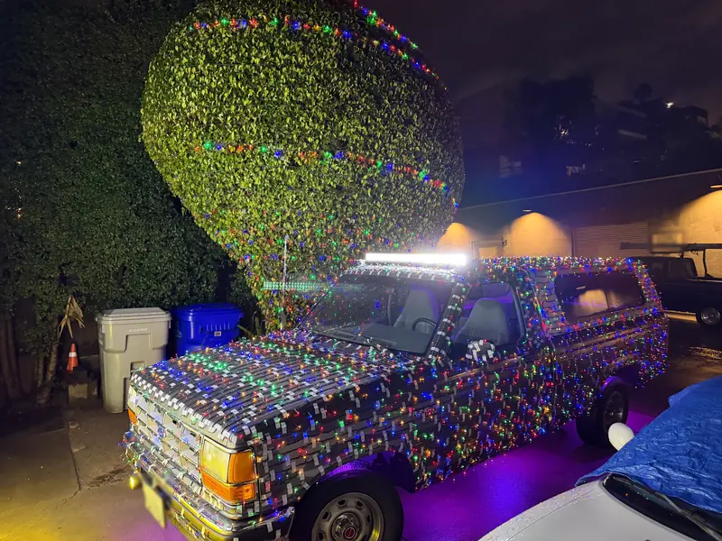
On the truck

Train-horn system

A genuine Nathan K5LA, re-voiced with a bell I modeled and printed, on a cage I built.

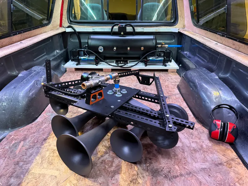
I adapted a genuine Nathan AirChime K5LA locomotive horn for my truck and re-voiced it toward a deeper, K5HL-style freight sound. I modeled and 3D-printed a replacement bell, printed inserts for two others, upgraded the air delivery and built the cage that mounts the horns in the old spare-tire spot.

The goal

A deeper, more aggressive freight-train sound from real locomotive hardware, instead of the horn’s brighter stock tone, plus a way to fit five bells, a tank and two compressors on a compact pickup.

The hard part

Making the 1L bell, a long bell that plays the lowest note. I swapped it in for the horn’s smallest, highest-pitched bell. Beyond reference photos, I couldn’t find the bell’s internal shape, so I worked out its flare in Fusion 360, using AI to help with the research, and revised it before 3D-printing the whole bell in PETG plastic. It has been tested at 175 psi without cracking. Then I printed inserts for two more bells, the 3A and 4A, to push the sound closer to a K5HL.

Air and mounting

I upgraded the solenoid (the electric valve that releases air into the horn) and the plumbing, bolted the air system into the bed, and built a heavy-duty cage from strut channel, angle and rebar. The cage bolts together and sits on bushings that isolate it from the frame. The air system usually runs at 150 psi, has been tested at 175, and also supplies my semi-truck horns.

Wiring

The horns are only part of what I’ve added to the truck, so I rewired it to match. Under the hood, I designed and 3D-printed boxes for relays, fuses and wire connectors. In the bed, a larger printed box collects the added circuits, which run through a 1-inch wire loom to the switch panels up front.

How it turned out

To my ear, the printed 1L made the biggest difference, giving the horn a deeper, more aggressive sound.

17 more photos. Scroll sideways, or tap one to open it full screen.

Team project

FTC competition robot

Team captain, primary designer and wiring lead for my FIRST Tech Challenge team’s 2024–25 robot.

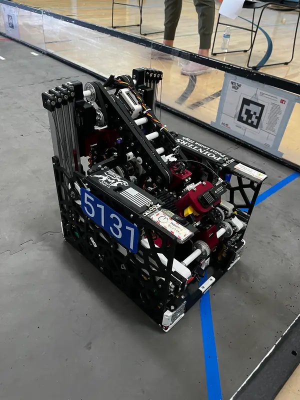
For the 2024–25 FIRST Tech Challenge season, I was team captain and the primary designer, assembler and wiring lead for Team 5131’s robot at Point Loma High School. We were a very small team, and a teammate handled the programming.

The challenge

That season’s game, INTO THE DEEP, had robots pick up game pieces called samples and score them in baskets, or hang clipped samples (specimens) on a raised bar. Each match starts with 30 seconds where the robot runs on its own, then two minutes of driver control, and robots can climb at the end for extra points.

Starting over

Our first robot took about three months to build. It was mostly acrylic and used one large arm to do everything, which made it slow and limited its reach. We scrapped it, started from scratch, and built the replacement in a little over a month.

The new design

The big change was splitting the work between two smaller arms: a horizontal mechanism picks up a game piece and passes it to a vertical lift that scores it high. The robot drives on mecanum wheels, so it can move in any direction. Odometry wheels underneath track its position, which lets it correct its course if another robot bumps it. At the end of a match, it can also climb, lifting itself off the floor.

Team results

Our team won the Innovate Award at the San Diego Turing League Tournament in February 2025, and ranked 13th of 36 in qualification at the San Diego Championship in March.

6 more photos. Scroll sideways, or tap one to open it full screen.

The autonomous period

0:30, with original sound. No one is driving: the robot runs on its own for the first 30 seconds of a match.

Team project

NASA Student Launch

Drawings, schematics and hands-on construction for Team Hydra’s rocket in NASA’s 2023 student competition.

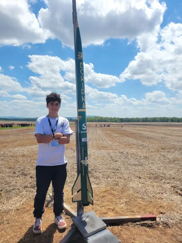
For Team Hydra’s 2022–2023 NASA Student Launch entry, I was the team’s mechanical and electrical design lead. I turned the design into CAD models, drawings and schematics, and helped build the rocket.

The competition

NASA Student Launch is a year-long rocketry challenge run by NASA. Teams design, build and fly a rocket that carries a payload, document the design along the way, and launch in the spring.

My part

I modeled parts and assemblies in CAD, turned them into dimensioned drawings the team could build from, and drew the electrical schematics and wiring diagrams that show how the electronics connect. My CAD work included the payload bay for a camera designed to rotate after landing and take panoramic photos; the payload worked most of the time. I also documented how the design developed.

How it turned out

We flew the rocket at the April 2023 launch. Our team placed third for Altitude, third for Judges’ Choice and second for STEM Engagement in the middle/high school division of NASA’s 2023 Student Launch.

Drawings

A few of the drawings I made for the project’s design documentation. Select one to see it full size.

Rocket assembly drawing: a section view of the parachutes, ejection charges and payload bay
Lower body tube assembly drawing: fins, centering rings and a dimensioned section view
Payload bay drawing: the camera, stepper motors and sleds, dimensioned in millimeters

3 more photos. Scroll sideways, or tap one to open it full screen.

Solo project

Electric trike

From plywood mockup to a rideable metal frame, built on request.

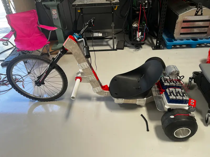
Someone asked me to build an electric trike, and I took it on for the fun of it. I designed and built the frame myself, from a plywood mockup to welded metal, then wired in the motor and electronics, which I bought. It’s rideable, with more work planned.

How it came together

  1. Built a plywood mockup to settle the size and proportions
  2. Moved the dimensions into Fusion 360 and refined the design
  3. Laser-cut the metal parts
  4. Welded and assembled the frame
  5. Wired the electric drive

What I’m proudest of

How fast it came together: the main design and build took about a week, from plywood mockup to a rigid metal frame.

5 more photos. Scroll sideways, or tap one to open it full screen.

A closer look at the assembly

0:06, with original sound

Solo project

Catapult

A spring-and-winch launcher, modeled and built solo for a school assignment.

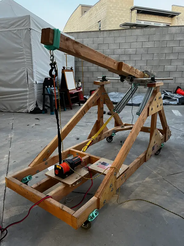
For a high-school assignment to build an animatronic, I chose a catapult. I modeled the whole thing in 3D and built it myself in a few weeks. It started as a candy launcher and ended up throwing pumpkins.

How it works

Eight garage-door extension springs power the throw. A winch pulls the beam down against them, and a quick release lets it go. The counterweight is adjustable: I can add weight or move it forward and back, and different attachment points change the spring tension.

What it’s made of

A 2×4 frame braced with quarter-inch plywood, plus custom 3D-printed parts: casters, shaft sleeves and counterweight brackets.

3 more photos. Scroll sideways, or tap one to open it full screen.

Outdoor demonstration

0:05, with original sound

Solo project

Level One rocket

A kit rocket I built, painted in four masked colors, and flew to earn my Level One certification.

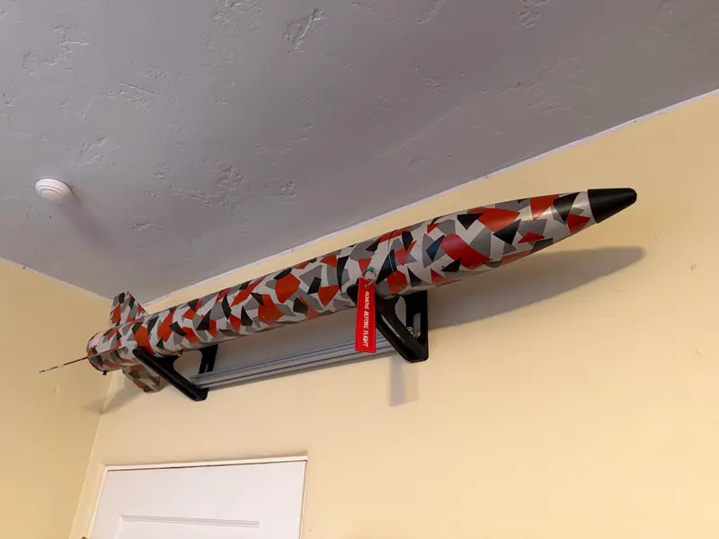
In 2022 I built a kit rocket in my garage in about a week, doing all of the epoxy work, woodworking and assembly myself. Its first and only flight, in April 2023, earned me my Level One certification. The part I’m proudest of is the paint job, which took more than seven hours.

The hard part

Not the rocket, the paint. The first coat was black; then I masked the triangle shapes and layered red, dark gray and light gray, masking on top of masking. Each layer hid earlier work, so the challenge was planning how much of each color would still show at the end.

How it turned out

The four colors cover roughly equal areas and work well together, which is what I was aiming for. Its one flight went well, and it came down under its parachute.

3 more photos. Scroll sideways, or tap one to open it full screen.

Peeling back the masking

0:04, with original sound

On the truck

Truck switch panels

Printed replacement trim that gives every added system its own switch.

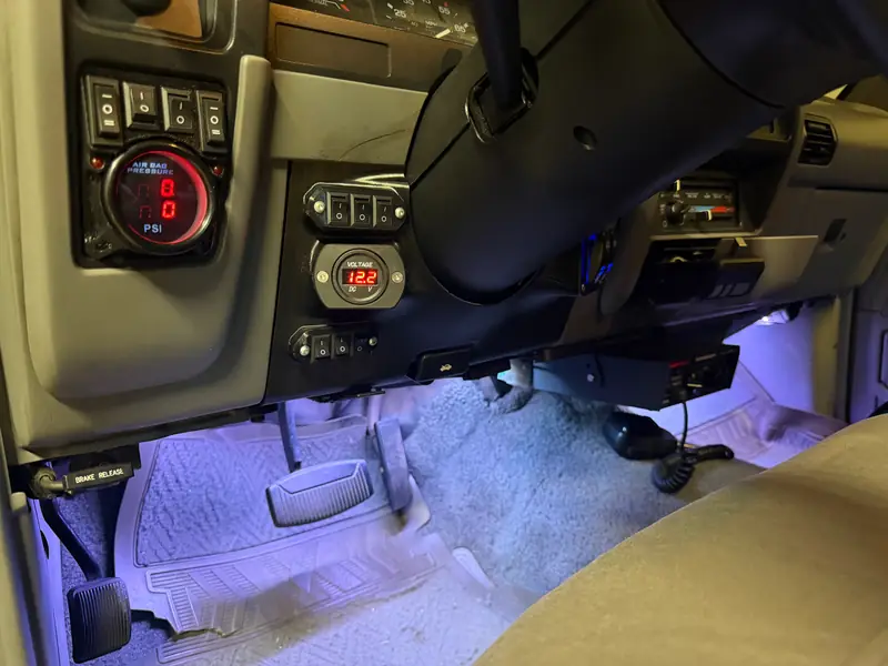
My truck has picked up a lot of added systems, and they all needed switches. Instead of drilling into the original steering-area trim, I reverse-engineered it and 3D-printed two replacement panels with cutouts for the controls.

What the switches control

  • The rear air tank: fill and release
  • The truck’s second electrical system
  • The horns: one switch picks the stock horn or the added horns, and three more choose which of them sound
  • Interior lights, bed-shell lights, rock lights and fog lights
  • The light bar
  • One spare switch for whatever I add next

Separately, I installed and wired a store-bought PA system in the truck.

Why printed

The original trim stays untouched. When the setup changes, I edit the model and reprint a panel instead of cutting into the truck. It’s one of my favorite truck projects.

5 more photos. Scroll sideways, or tap one to open it full screen.

On the truck

Light-bar mounts

Adjustable suction-cup mounts that hold a 52-inch light bar on my cab roof without drilling.

I came across a secondhand light bar on Facebook Marketplace that happened to be 52 inches, a good fit for my Ranger’s cab roof. I didn’t want to drill holes in the truck, and I couldn’t find a mount online that would work, so I designed and 3D-printed my own mount that sits on four suction cups.

How it adjusts

Each support pivots on all three axes, so the suction cups follow the curve of the roof. That adjustability was intentional: I wanted a mount I could also set up on other vehicles or use with other lights, not one made for a single roof.

The hard part

Getting the hinges and printed connections right, so four flat suction cups could sit on the curved roof instead of being forced onto one plane. There’s only just enough room on the roof for all four cups.

6 more photos. Scroll sideways, or tap one to open it full screen.

The mounts articulating

0:10, with original sound

On the truck

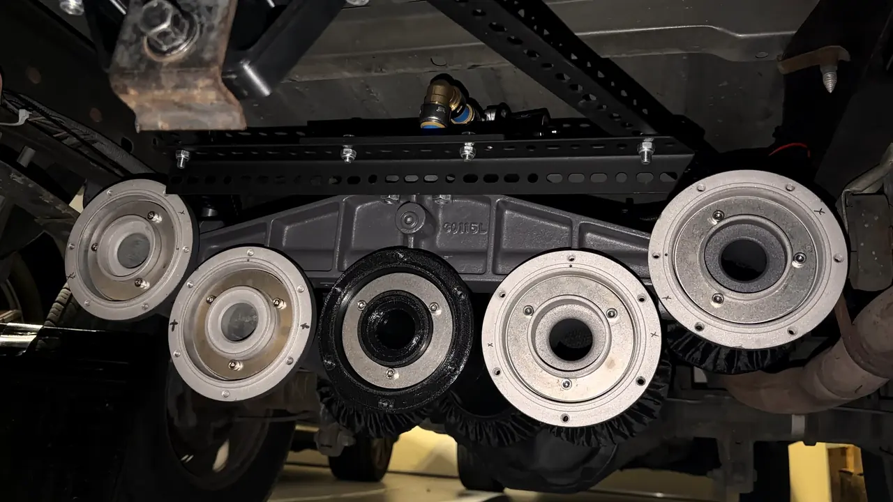
Semi-truck horns

Four semi-truck air horns under my Ranger, on a custom mount I designed and built.

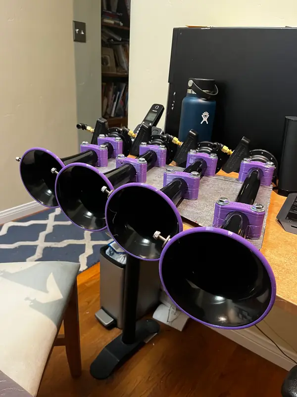
In 2023 I bought a set of semi-truck air horns for my Ranger, but they didn’t come with any way to fit a truck this size. So I designed and built my own mount: a sheet-metal plate that holds all four horns as one unit, with 3D-printed parts and supports. Then I installed it under the truck and did the wiring and plumbing.

Shock-absorbing parts

Everything purple is 3D-printed in TPU, a flexible, rubber-like plastic. It works like a grommet, soaking up road shock so the horns don’t get beaten up while I drive.

Air supply

They started on a small 2-gallon tank and compressor. When I built my train-horn system, I upgraded to an 8-gallon tank with dual compressors, and now both horn sets run from it.

How it turned out

Both sets are still on the truck, and I can sound either one on its own or both together. To my ear, the combination is deep and unusual, and it echoes and carries a long way.

5 more photos. Scroll sideways, or tap one to open it full screen.

On the truck

Bluetooth receiver

A plug-in car adapter rebuilt as a tidy module with a printed housing and buttons.

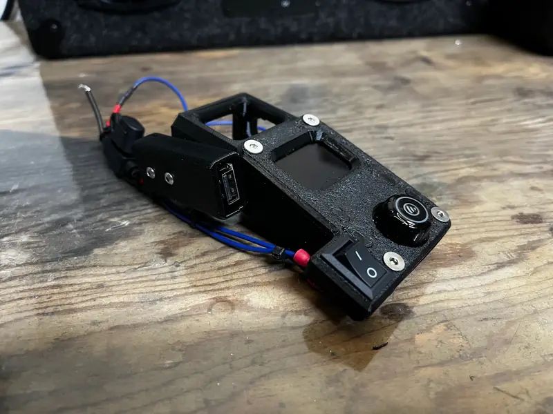
I took apart a plug-in Bluetooth car adapter and rebuilt it as its own module, with a 3D-printed housing and buttons. It sits in the dash tray instead of sticking out of the outlet, which leaves the outlet free.

What I did

I opened up the adapter, soldered and wired USB connections for phone charging, then designed and printed a housing for the board and new buttons for its controls.

5 more photos. Scroll sideways, or tap one to open it full screen.

Solo project

Speaker enclosure

A carpeted wooden enclosure designed and built around a speaker kit.

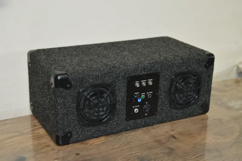
A summer project to learn woodworking: I designed and built a carpeted enclosure around a speaker kit I bought.

How it went together

I modeled the box and its openings in Fusion 360, built an inner wooden frame, added plywood panels, then carpeted the outside. Last, I modeled the driver grilles and printed them in black.

How it turned out

Looks were the main goal, and that’s what I’m happiest with. To my ear, it sounds great too.

7 more photos. Scroll sideways, or tap one to open it full screen.

Solo project

RC car modifications

Lighting, cooling and 3D-printed upgrades for my RC cars, plus LED kits I made and sold.

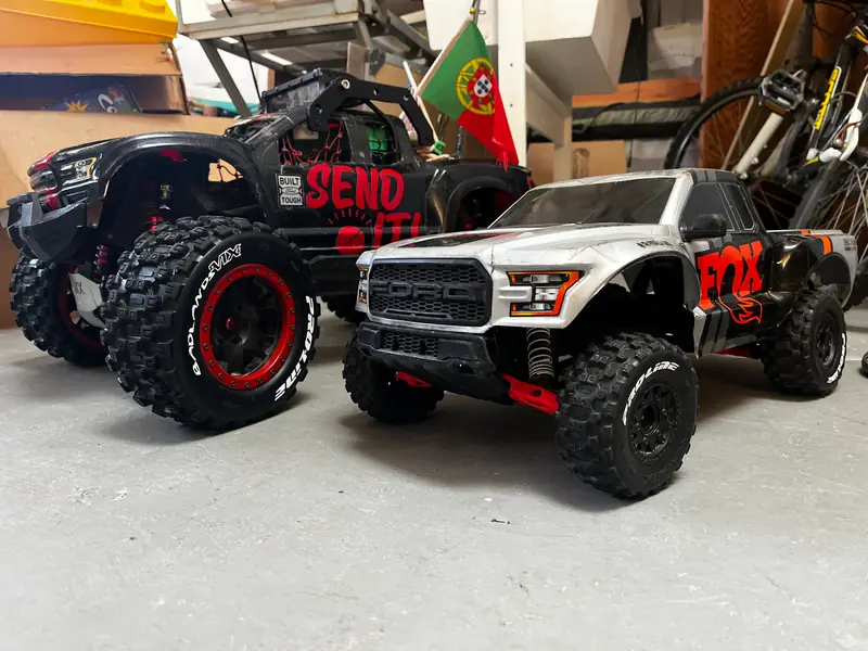
In high school I modified my RC cars for both performance and looks, mostly with lighting. My Traxxas X-Maxx got the most work. I also designed wheels for my smaller 1/10-scale Traxxas Slash, and I made LED light kits for RC cars and sold them on eBay.

The X-Maxx

Two fans push air over the speed controller (ESC) and brushless motor. A 3D-printed roll cage helps protect the body during rollovers, and weak spots got printed parts or aluminum replacements, including all-aluminum steering. For lighting, it has headlights, rock lights, two light bars (one on the roof, one up front) and a lot of rear lights.

The Slash wheels

I designed rims and tires for the Slash in Fusion 360 and 3D-printed them.

7 more photos. Scroll sideways, or tap one to open it full screen.

Capabilities

CAD modeling
Fusion 360: the horn bell profile, switch panels, light-bar mounts, trike frame, enclosures, RC rims and rocket payload parts
Technical drawing
Dimensioned mechanical and assembly drawings, electrical schematics and wiring diagrams for a NASA Student Launch team rocket
Reverse engineering
Modeling replacement switch panels from my truck’s original trim, so the original parts stay untouched
3D printing and prototyping
Functional printed parts, from a full-size PETG horn bell to flexible TPU horn mounts, plus quick prototypes like the trike’s plywood mockup
Fabrication and welding
The trike’s laser-cut, TIG-welded frame, the horn system’s bolted mounting cage and sheet-metal horn mounts
Mechanism design
An FTC robot’s two-arm pickup-and-scoring system, articulated light-bar mounts and an adjustable spring-powered catapult
Pneumatics and plumbing
Two horn systems on one air supply: an 8-gallon dual-compressor system, solenoid valves, automatic drain valves and the plumbing between them
Electrical and wiring
The Ranger’s added accessory systems, the trike’s electric drive, an FTC competition robot and soldered USB charging
LED lighting
LED light kits for RC cars that I made and sold on eBay, and the lighting on my own RC cars and truck
Rocketry
Level One certified with a kit rocket I built, plus drawings and construction for a NASA Student Launch team rocket
Woodworking
The speaker enclosure and its carpet finish, the catapult’s 2×4 and plywood frame, and a kit rocket’s assembly
Painting
A four-color paint job on a kit rocket, masked layer by layer so each color ends up in the right place

Each build lists what was bought and what I designed and made, so my contribution is clear.

About

I’m Aaron Gilbert, and I live in San Diego. I’m studying business management at San Diego Mesa College and plan to transfer to Penn State or SDSU; my goal is a career on the entrepreneurial side. Engineering is what I do for fun: most of my projects start as a model in Fusion 360 and get built in my garage, many of them for my 1992 Ford Ranger. Outside of my projects, I love snowboarding, surfing and mountain biking.

I’ve been on robotics and rocketry teams since middle school, including Point Loma High School’s FTC team and a NASA Student Launch team. Through middle and high school, I also ran Aaron’s MOC Shop, a custom LEGO store on BrickLink that passed 500 orders.

Contact

The best way to reach me is email.